
Heat pipe-cooled highly-concentrated multi-junction solar cell
- Physics Department, College of Science, Umm Al Qura University, Makkah, Kingdom of Saudi Arabia
- Solar Physics Lab, National Research Institute of Astronomy and Geophysics, Cairo, Egypt
- Physics Department, Faculty of Science, Mansoura University, Mansoura, Egypt
Article Info
Received 08 Jan. 2024
Received in revised form 22 Feb. 2024
Accepted 27 Feb. 2024
Available on-line 20 Mar. 2024
Keywords: Solar cell; concentrator photovoltaics (CPV); heat pipe (HP); passive cooling; PV performance.
Abstract
Concentrator photovoltaic (CPV) systems have proven the capability of competing with traditional photovoltaic (PV) systems due to their high efficiency and low area occupancy. Such CPV systems require efficient heat removal auxiliary systems, especially for medium and high optical concentration ratios. Operating a CPV system under a high optical concentration (ratio > 200 X) might require active cooling techniques, which have high operating costs and maintenance. On the other hand, heat pipes (HPs) are widely used in electronic devices for cooling purposes. This work discusses the possibility of operating a CPV system coupled with HPs as a passive cooling technique. Two different HPs with different lengths are used to compare cooling efficiency. Each HP length was tested either in a single or double configuration. Long HPs showed better heat removal compared to a traditional fin-cooling system. CVP cooling with HP systems enhanced the entire electrical output of the cell, mainly at high optical concentration ratios.
Introduction
Concentrator photovoltaics
Reliability, durability, and availability, in addition to the green impact on the environment, are among the main characteristics of photovoltaics [1]. As a way to reduce solar cell area, hence cost, concentrator photovoltaic (CPV) systems are used to increase the solar radiation intensity incident on the solar cell area by using mirrors or lenses, depending on the solar concentration ratio required [2–4]. However, CPV technology has its own challenges such as sun tracking and PV cooling [5].
The concentrated solar radiation elevates the operating temperature of the solar cells, resulting in reducing its output voltage, hence its output power [6]. The majority of the characteristics of the solar cell parameters are impacted by temperature increase. An increase in temperature causes the band gap to shrink, what negatively impacts the open-circuit voltage. On the other hand, as the band gap energy decreases, more photons have enough energy to create electron-hole pairs, resulting in a slight increase of the short-circuit current. PV power generally experiences a drop with increasing temperature.
Reducing the CPV system temperature is also important in order to avoid solar cell failure due to different expansion coefficients between the solar cell interconnecting materials and the substrate. Moreover, the number of thermal cycles and the magnitude of thermal excursion affect the receiver reliability. The solar cell temperature uniformity also has some influence on conversion efficiency [7].
To overcome such temperature drawbacks, a proper cooling system must be combined with such CPV system for decreasing the cell temperature and, hence improving PV efficiency. Although active cooling may be used to overcome this temperature increase, it adds to the total system cost and maintenance requirements.
Passive cooling, on the other hand, may represent a better solution for such problems.
Cooling methods differ from one CPV system to another [8, 9]: for a single cell, passive cooling might be effective; for a single 1 cm2 cell, passive cooling using a heat sink has proven to be a good choice for optical concentration ratios of up to 500 X [6]. In comparison, active cooling is effective for densely packed cells and linear concentrators [6].
GaInP/GaAs/Ge multi-junction CPV devices have high efficiency under high optical concentration (~ 500 X or higher) provided that their operating temperatures do not exceed 100–120 °C [10, 11]. The characteristics of the multi-junction CPV system could be described mathemati-cally by the one-diode model (1)
\( I=I_L-I_0 \cdot\left[e^{\frac{q\left(V+I R_s\right)}{n k T}}-1\right]-\frac{V+I R_s}{R_{s h}} \) (1)
where 𝐼L is the photo-generated current, 𝐼0 is the reverse saturation current, 𝑇 is the absolute temperature, 𝑞 is the elementary charge, 𝑘 is the Boltzmann’s constant, 𝑛 is the diode ideality factor, and 𝑅𝑠, 𝑅𝑠ℎ are the series and shunt resistances of the solar cell, respectively.
Degradation of open-circuit voltage with increasing cell temperature is expressed mathematically in (2) [12]
\( \begin{aligned} \frac{\partial V_{o c}}{\partial T} \approx & -\frac{1}{T}\left[\frac{n}{q} \cdot E_g-V_{o c}+\frac{n k T}{q} \cdot\left(3+\frac{\gamma}{2}\right)\right]+\frac{n k T}{q} \\ & \cdot \frac{1}{J_{s c}} \cdot \frac{\partial J_{s c}}{\partial T}+\frac{n}{q} \cdot \frac{\partial E_g}{\partial T} \end{aligned} \) (2)
where 𝐸𝑔 is the absorber band gap and 𝐽𝑠𝑐 is the open-circuit current density. Parameter 𝛾 is the constant to incorporate the temperature dependence of other material parameters. The fill factor (FF) of a solar cell is the ratio of the maxi-mum power extracted to the product of the open-circuit voltage and short-circuit current, as expressed in (3) [13, 14]
\( F F=\frac{I_m V_m}{I_{s c} V_{o c}}=\frac{V_m}{V_{o c}}\left[1-e^{\frac{q}{n k T}\left(V_m-V_{o c}\right)}\right] \) (3)
where 𝐼𝑚 and 𝑉𝑚 are the current and voltage at the maximum power point and 𝐼𝑠𝑐 is the short-circuit current. Efficiency of the solar cell (n) is the ratio between the maximum output power obtained from the cell and the input power; this is mathematically expressed in 4 [13, 14] as
\( \eta=\frac{I_m V_m}{P_{i n} \cdot A} \) (4)
where 𝑃𝑖𝑛 is the input power, and 𝐴 is the area of the solar cell. Solar cells performance is very sensitive to the operating temperature because it reduces the cell band gap. Therefore, all cell parameters are closely related to its operating temperature. While the cell current increases slightly, the cell voltage, and thus its output power, are significantly reduced. The CPV cells mentioned in this work are three-junction devices (C1MJ) manufactured by Spectrolab [6, 15–17], which have a recorded efficiency of 37 % under 500 W/m2 of illumination at a temperature of 25 C. Temperature coefficients of the CPV device used here are −4.3 mV/C and −0.06 %/C corresponding to open-circuit voltage and efficiency, respectively [17].
Heat pipes
The heat pipe (HP) shown in Fig. 1 is a tool that facilitates the quick and effective extraction of heat. A closed, deflated tube with a solid outer surface is the first layer of the HP which is followed by a layer of a porous metal (wick). The interior portion of the HP has pores that are partially filled with a working fluid that repeatedly switches between the liquid and vapour phases to transmit heat [18, 19].
One end of the tube, the evaporator, is brought into thermal contact with a heated object to be cooled and the other end, the condenser, is connected to a heat sink or fins to disperse heat. Since there are no heat exchanges taking place in this region, the tube body between the evaporator and the condenser is referred to as the adiabatic section [20].
Heat is taken in the evaporator part of the HPs, which causes the liquid in the wick layer to change into the vapour phase. Due to the pressure differential between the two ends, the vapour moves toward the cold part of the condenser at the other end where it releases heat and condenses to the liquid phase before returning to the evaporator section within the wick layer. As long as there is a temperature differential between the condenser and evaporator, this two-phase circulation will continue [21].
CPV/HP-coupled system
Different methods have been used for the passive cooling of the concentrator solar cells. Fins could be used by attaching them directly to the back of the CPV system [22]. Micro-finned heat sinks were also used for the same purpose [23]. In the authors' previous work, a coupled passive CPV/TEG system was used to remove heat from a solar cell, and additional power generation using thermos-electric generators was recorded [24]. HPs have been used as cooling solutions for PV applications. For example, a proposed design of HP cooling for CPV system has been presented and analysed in Ref. 25. In addition, PV panel cooling under non-concentrated incident solar radiation using HP has been tested [26] and a reduction of panel temperature of 15–30% has been recorded.
Given the advantages of a stationary, silent, and power-free cooling system, this work investigates the possibility of using HPs to passively reduce the CPV system temperature for maintaining its efficiency at acceptable levels. Different configurations have been used and their performances have been compared to that of a simple fin-cooled CPV system.
Experimental setup
Experimental setup is shown in Fig. 2. The CPV cell has been thermally attached to a copper block using a thermal wax with high thermal conductivity: (> 1.829 Wm−1K−1).
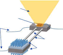

The evaporator ends of two HPs have been fitted in two suitable holes in the copper block using thermal wax. The other ends of the HPs were attached to two sets of fins attached on both sides of another copper block. The CPV system and the thermally attached cooling system including the HPs were kept horizontal during all phases of the experiment. Controlled concentrated light falls only on the CPV cell surface using a diaphragm to avoid irradiating the copper block directly. Table 1 lists the properties of the high concentration solar simulator used where the light intensity is varied from 70 to 260 kW/m2, and the performance of the system is tested accordingly.
The I-V characteristics of the CPV system were measured by connecting the two CPV terminals to the source meter. At the same time, temperatures of the evaporator, as well as the fin-cooled condenser are measured simultaneously using thermocouples attached to them. All measurements are recorded after the steady state is reached.
Table 1.
Properties of the high concentration solar simulator used..
Parameter |
Value |
Area illuminated |
Square area of side length of 0.1 m |
Spatial uniformity |
< ± 2.5% over the illuminated area |
Collimation half angle |
< ± 2.5° |
Temporal instability |
Class A |
Spectral match |
Class B for ASTM AM1.5G |
Results and discussion
Four different configurations of HPs have been tested: (i) one long HP, (ii) one short HP, (iii) two long HPs, and (iv) two short HPs. The performance of all these configurations is also compared to that of the traditional static fincooling system (i.e., the cell is attached directly on top of the fins).
Fig. 3 shows a comparison of cell temperature of all cooling configurations tested. Using HPs in all configurations showed a significant reduction in cell temperature compared to that of the traditional fin-cooled system.

At an illumination concentration of about 250 X, the traditional fin-cooled cell was at a temperature over 140 °C. However, the temperature was reduced to about 122 °C and 114 °C for the short and the long single HPcooled systems, respectively. The two HP-based systems showed further temperature reduction. At an optical concentration ratio of 260 X, the cell temperatures further decreased to 115 °C and 108 °C with two short and two long HPs, respectively, compared to about 140 °C for the fin-only system as mentioned previously. Under the illumination range investigated in this work, starting from about 90 X up to 250–260 X, the absolute maximum increase in temperature for each cooling configuration (including the fin-only system) was around 50 °C or more. However, the two long HPs-based system is the only exception with its absolute maximum increase in the cell temperature being around 39 °C, which demonstrates the high heat extraction capability of this configuration.
Due to such improved cooling, the PV working parameters of the solar cell have been enhanced. Moreover, the performance of the HP-based cooling systems becomes superior at higher illumination intensity (as discussed later), which makes such systems more preferable in actual applications of CPV. Although each working parameter of the CPV cell improved by each HP-based system has been tested in this work, the discussion below focuses on the comparison between the two long HPs-based configuration and the control because this configuration showed the best overall results among all other configurations, especially at high illumination intensity.
In Fig. 4, the change in the cell open-circuit voltage (𝑉𝑜𝑐) is shown as a function of illumination intensity for all cooling configurations. At the lowest illumination intensity investigated (90 X), using the two long HPs system, 𝑉𝑜𝑐 showed an increase by 4.8% compared to that of the finonly cooled system. However, this improvement in 𝑉𝑜𝑐 is more pronounced at the highest illumination where the ratio increased to 14.3%. The improvement in the 𝑉𝑜𝑐 values is indeed expected as the cell is cooled down. However, this result demonstrates the gain in the output voltage by using the two long HPs system. Having the condenser ends of the HPs at a further distance from the hot cell (i.e., in the case of the long HPs compared to that of the short HPs) could be the main reason for this superior cooling performance.
It is well known that HP cooling efficiency depends on various factors, among which is the temperature gradient between its ends. Thus, using the long HPs in the present configuration could create a more preferable temperature gradient across the long HPs compared to the temperature gradient of the short ones. This effect is more pronounced under high light intensity, which can be understood because high light intensity creates a higher temperature at the cell (and thus alters the temperature gradient, as well).
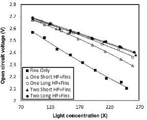
Fig. 5 demonstrates the effect of illumination intensity on the short-circuit current (𝐼𝑠𝑐), which shows that all cooling configurations did not have a noticeable effect on 𝐼𝑠𝑐. Although the 𝐼𝑠𝑐 is supposed to increase with increasing temperature, 𝐼𝑠𝑐 is known to be, arguably, the least affected PV working parameter by the elevation of temperature. Materials with high trap concentration would show a weak dependence of 𝐼𝑠𝑐 on temperature. As mentioned above, the device tested in this work is a three-junction cell consisting of several layers. The mismatch in the lattice constant between each two consecutive layers beside the grain boundaries in each material in the device may create a high density of traps in each band gap in the cell. Thus, the effect of temperature on 𝐼𝑠𝑐 due to the increase of the illumination intensity itself may have masked the effect of the tempera-ture reduction due to the cooling systems tested in this work.

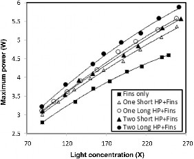
Cooling the cell using the HP systems also enhanced the device electrical output, especially at higher optical concentration ratios, as shown in Fig. 6. At low illu-mination intensity, the maximum power point (MPP) of the device has increased by 14.3% when two long HPs are used in the cooling system in comparison with the fin-only system. The increase in MPP jumped to around 28.3% at high illumination intensity (comparing the same two systems, i.e., two long HPs vs. fin-only systems). The increase in the MPP is a direct result of the improvement in the output voltage of the cell. The most striking result, however, is the degree of increase in the MPP value. Having more than 28% of extra output power by a simple and passive cooling system is indeed significant.
To illustrate the effect of cooling enhancement due to such HPs, Fig. 7 shows the CPV system maximum power as a function of cell temperature in the case of using two short and two long HPs.

FF and PV conversion efficiency vs. light optical concen-tration ratio for four different HP cooling configurations along with the fin-only cooling are shown in Fig. 8 and Fig. 9, respectively. Comparing two long HPs system with the fin-only system, FF improved by 5.8% and 8.6% under low and high illuminating intensities, respectively. The FF value of the device increases with increasing 𝑉𝑜𝑐, therefore, it is expected that the FF values improve with efficient cooling as shown here. Moreover, the FF value depends on various other factors such as parasitic resistances and carrier recombination in the cell, which are themselves sensitive factors in temperature. The exact change in these factors as functions of cell temperature is out of the scope of this article. However, the heat dissipation achieved by using the cooling systems in this work has an overall positive effect on all these factors, which, therefore, improved the FF value itself as demonstrated in Fig. 8.

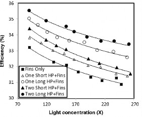
As a consequence of all the improvements mentioned above, the PV conversion efficiency of the cell also showed a significant improvement due to the applications of the HPs-based cooling systems compared to the fin-only system. This improvement is maximized when two long HPs are used under high illumination intensity, as expected. The PV conversion efficiency increased by 6.9% at low illumination intensity, whereas it was 8.1% under high intensity.
Conclusions
Passive cooling of CPV systems using HPs has been investigated. Four different arrangements were examined using either: one or two (short or long) HPs. Another configuration based on a traditional fin-only cooling system was used as a control in this study. The cooling systems implementing HPs can reduce the cell temperature significantly. Such a temperature reduction enhances all the PV working parameters of the cell and increases the overall PV performance. The improvement in the cell performance in each working parameter was systematic over the illumination range investigated in this work. This implies that using the proposed cooling configuration is indeed effective and beneficial. Although each HP-based system tested in this work outperformed the fin-only cooling system, the configuration with two long HPs shows the best performance among all other configurations. The results of this work show that implementing HPs in the passive cooling systems for CPV is very promising. The HPs may provide new affordable, unsophisticated, and low-maintenance solution for reducing the deleterious effect of high temperature on CPV systems.
Conflict of interest
Authors declare no conflict of interest.
Funding
This work was self-funded by the authors.
Authors’ statement
All authors have contributed equally to the paper, read and approved the final version of the manuscript. The research concept and design, the collection and assembly of data, as well as their analysis and interpretation, the writing of the article, as well as the critical revision and the final approval of the article have been performed by all authors.
References
-
Singh, G. K. Solar power generation by PV (photovoltaic) technology: A review. Energy 53, 1–13 (2013). https://doi.org/10.1016/j.energy.2013.02.057
-
Du, B., Hu, E. & Kolhe, M. Performance analysis of water cooled concentrated photovoltaic (CPV) system. Renew. Sustain. Energy Rev. 16, 6732–6736 (2012). https://doi.org/10.1016/j.rser.2012.09.007
-
Abo-Zahhad, E. M., Ookawara, S., Radwan, A., El-Shazly, A. H. & ElKady, M. F. Thermal and structure analyses of high concentrator solar cell under confined jet impingement cooling. Energy Convers. Manag. 176, 39–54 (2018). https://doi.org/10.1016/j.enconman.2018.09.005
-
Abo-Zahhad, E. M. et al. Performance, limits, and thermal stress analysis of high concentrator multi-junction solar cell under passive cooling conditions. Appl. Therm. Eng. 164, 114497 (2020). https://doi.org/10.1016/j.applthermaleng.2019.114497
-
Luque, A. & Hegedus, S. Handbook of Photovoltaic Science and Engineering. (John Wiley & Sons, 2011).
-
Theristis, M. & O’Donovan, T. S. Electrical-thermal analysis of III– V triple-junction solar cells under variable spectra and ambient temperatures. Sol. Energy 118, 533–546 (2015). https://doi.org/10.1016/j.solener.2015.06.003
-
Anderson, W. G., Dussinger, P. M., Sarraf, D. B. & Tamanna, S. Heat Pipe Cooling of Concentrating Photovoltaic Cells. in 33rd IEEE Photovolatic Specialists Conference 1–6 (IEEE, 2008). https://doi.org/10.1109/PVSC.2008.4922577
-
Chen, J., Yang, L., Zhang, Z., Wei, J. & Yang, J. Optimization of a uniform solar concentrator with absorbers of different shapes. Sol. Energy 158, 396–406 (2017). https://doi.org/10.1016/j.solener.2017.09.061
-
Wang, S. et al. Cooling design and evaluation for photovoltaic cells within constrained space in a CPV/CSP hybrid solar system. Appl. Therm. Eng. 110, 369–381 (2017). https://doi.org/10.1016/j.applthermaleng.2016.08.196
-
Ibrahim, K. A., Luk, P. & Luo, Z. Cooling of concentrated photo- voltaic cells—a review and the perspective of pulsating flow cooling. Energies 16, 2842 (2023). https://doi.org/10.3390/en16062842
-
King, R. R. et al. Band-Gap-Engineered Architectures for High- Efficiency Multi-Junction Concentrator Solar Cells. in 24th European Photovoltaic Solar Energy Conference 1–7 (Spectrolab, Inc., 2009).
-
Cotal, H. et al. III–V multi-junction solar cells for concentrating photovoltaics. Energy Environ. Sci. 2, 174–192 (2009). https://doi.org/10.1039/B809257E
-
Nishioka, K. et al. Annual output estimation of concentrator photovoltaic systems using high-efficiency InGaP/InGaAs/Ge triple-junction solar cells based on experimental solar cell’s characteristics and field-test meteorological data. Sol. Energy Mater. Sol. Cells 90, 57–67 (2006). https://doi.org/10.1016/j.solmat.2005.01.011
-
Qu, H. & Li, X. Temperature dependency of the fill factor in PV modules between 6 and 40 °C. J. Mech. Sci. Technol. 33, 1981–1986 (2019). http://doi.org/10.1007/s12206-019-0348-4
-
Singh, P. & Ravindra, N. M. Temperature dependence of solar cell performance—an analysis. Sol. Energy Mater. Sol. Cells 101, 36–45 (2012). https://doi.org/10.1016/j.solmat.2012.02.019
-
CDO-100 Concentrator Photovoltaic Cell. Spectrolab. (2008). https://www.yumpu.com/en/document/read/26489114/cdo-100-concentrator-photovoltaic-cell-spectrolab
-
Min, C. et al. Thermal analysis and test for single concentrator solar cells. J. Semicond. 30, 044011 (2009). https://doi.org/10.1088/1674-4926/30/4/044011
-
Kinsey, G. S., Pien, P., Hebert, P. & Sherif, R. A. Operating characteristics of multi-junction solar cells. Sol. Energy Mater. Sol.Cells 93, 950–951 (2009). https://doi.org/10.1016/j.solmat.2008.11.053
-
Faghri, A. & Zhang, Y. 11-Two-Phase Flow and Heat Transfer. in Transport Phenomena in Multiphase Systems (eds. Faghri, A. & Zhang, Y.) 853–949 (Academic Press, Boston, 2006). https://doi.org/10.1016/B978-0-12-370610-2.50016-7
-
Reay, D., McGlen, R. & Kew, P. Heat Pipes: Theory, Design and Applications. (Butterworth-Heinemann, 2013).
-
Sangdot, R. & Patel, H. A review on photovoltaic panel cooling using heat pipe. Int. J. Sci. Res. 1, 573–576 (2016). https://www.ijsdr.org/papers/IJSDR1605109.pdf
-
Micheli, L., Fernandez, E. F., Almonacid, F., Reddy, K. S. & Mallick, T. K. Enhancing ultra-high CPV passive cooling using least-material finned heat sinks. AIP Conf. Proc. 1679, 130003 (2015). https://doi.org/10.1063/1.4931563
-
Micheli, L., Senthilarasu, S., Reddy, K. S. & Mallick, T. K. Applicability of silicon micro-finned heat sinks for 500× concentrating photovoltaics systems. J. Mater. Sci. 50, 5378–5388 (2015). https://doi.org/10.1007/s10853-015-9065-2
-
Lashin, A., Al Turkestani, M. & Sabry, M. Concentrated photovoltaic/thermal hybrid system coupled with a thermoelectric generator. Energies 12, 2623 (2019). https://doi.org/10.3390/en12132623
-
Anderson, W., Tamanna, S., Sarraf, D., Dussinger, P. & Hoffman, R. Heat Pipe Cooling of Concentrating Photovoltaic (CPV) Systems. in 6th International Energy Conversion Engineering Conference (IECEC) TM-3 (American Institute of Aeronautics and Astro- nautics, Inc., 2008). https://doi.org/10.2514/6.2008-5672
-
Habeeb, L., Ghanim, D. & Muslim, F. Cooling photovoltaic thermal solar panel by using heat pipe at Baghdad climate. Int. J. Mech. Eng. 17, 171–185 (2017).