The expected performance analysis of a retroreflector-supported inter-satellite laser rangefinder designed for Polish ImAging SaTellites (PIAST) space mission
- Institute of Optoelectronics, Military University of Technology, ul. gen. S. Kaliskiego 2, 00-908 Warsaw, Poland
Article Info
Received 25 Jan. 2024
Received in revised form 09 Apr. 2024
Accepted 24 Apr. 2024
Available on-line 06 Jun. 2024
Keywords: Laser rangefinder; corner cube retroreflector; far-field diffraction pattern; imaging from space.
Abstract
The paper provides a detailed treatment of the expected range performance for the laser rangefinder (LRF) developed for the Polish ImAging SaTellites (PIAST) space mission, where the distance between satellites within a constellation has to be measured during orbital flight. The satellites are equipped with corner cube retroreflectors (CCR) to increase the efficiency of laser back-reflection. A theoretical signal-to-noise range-dependence model was developed to determine the maximum expected range of the measurements. This model included the tilt-angle-dependent properties of the CCR far-field diffraction patterns (FFDP) which were measured experimentally. In addition, the specific parameters of the receiving optoelectronic circuit used were considered. The obtained results show that in the case of the constructed PIAST LRF (peak laser pulse power of 100 W, laser beam divergence of 5 mrad, receiving optical aperture diameter of 2 in, CCR diameter of 2 in), depending on the CCR angular inclination, a maximum measurement distance of 15–40 km is expected.
Introduction
The increasing number of small satellites in space (nanosatellites and CubeSats) has driven a rapid develop-ment of miniaturised equipment technologies suitable for such carriers. This means that all sensors, communication and navigation modules, supply blocks, and propulsion components if planned to be applied on a compact satellite, have to be prepared in a ‘small, lightweight and low-power-consumption’ version. Sometimes, such a demand for miniaturisation while maintaining performance at the same or even higher level goes against the constraints of physics or limitations of currently available technical capabilities.
This case is addressed in this study. The primary goal of the Polish ImAging SaTellites (PIAST) mission is to achieve super-resolution imaging thanks to the cooperation of several imaging instruments distributed on different satellites within the constellation and to capture the scene exactly at the same time. Precise satellite-to-satellite (instrument-to-instrument) distance mapping is required for algorithms to achieve an exceptional level of imaging performance.
According to the PIAST mission requirements, the authors’ task was to develop a laser rangefinder (LRF) that should be miniaturised and have low power; however, it has a very large-range measurement capability (the maximum range above 10 km and measurement accuracy of cm). It had to be suitable for small-satellite imple-mentation, which was planned to measure distances to other satellites within the same constellation. The LRF application for this task is crucial because satellite positioning based solely on global navigation satellite systems (GNSS) does not provide the required level of precision. Considering systems such as GPS used for precise and real-time positioning of fast-moving objects (satellites) in orbit, a distance measurement accuracy would be on the order of single meters and data would be provided with significant time delay. This is far below the requirements of many technological and scientific challenges in space, including the PIAST. Apart from the limited capabilities of GNSS, another factor of high importance in the current uncertain global situation is its susceptibility to disruption or destruction. Therefore, it is necessary to review existing range-finding technology and identify the most suitable solution for the PIAST mission.
Development of the space-oriented range-finding technology is an active research topic; therefore, its choices are wide. Various technologies have been implemented depending on the desired maximum range and distance measurement precision. In many research programs associated with, for example, gravitational wave monitoring or relativistic phenomena analysis, range measurement is a key factor. The most precise methods are based on interferometry and achieve nanometer-level precision. For example, NASA developed a laser ranging interferometer (LRI) that uses laser interferometry to measure small fluctuations in the separation between two GRACE-FO and FO spacecraft [1]. This instrument was designed for gravitational wave research. Jang et al. [2] discussed a combination of interference and a time-of-flight (ToF) technique where femtosecond pulses are applied. The outstanding precision of a single nanometer was obtained at a distance of 700 m. Traditional ToF techniques do not offer such remarkable accuracy; however, much larger distances can be measured. Direct ToF techniques (dToF) are based on pulsed laser sources and do not require a long coherence time for the emitted light. The range is calculated from a precise measurement of the time taken for the laser pulse to travel to the target and for the optical echo to return. Typically, short (nanosecond or tens of nanosecond) pulses are used to obtain a reasonable range of measurement accuracy. Indirect ToF (iToF) techniques are based on continuous-wave (CW) lasers which are amplitude-modulated. The receiver evaluates the phase shift between the emitted and detected waveforms. iToF techniques offer higher accuracy than dToF, but at the cost of a shorter maximum range capability. For this reason, in applications where large distances must be measured (military and space), dToF LRFs are most commonly used. Techniques based on the coherent detection of light according to heterodyne or homodyne detection schemes also exist. Since the received echo signal must interact coherently with the local oscillator, this technology requires application of laser sources with long coherence lengths. Modulation of the laser frequency enables to overcome range ambiguity and obtain the capability of measuring long ranges with high precision [3].
There is a wide selection of range-finding technologies. However, several key factors must be taken into account when considering LRF according to the PIAST mission requirements:
- maximum range that can be measured (> 10 km),
- measurement accuracy (> 10 cm),
- based on space-qualified components,
- possibility of constructing a miniature module (not exceeding 12 × 10 × 8 cm),
- low-power consumption (< 5 W),
- low weight (< 250 g).
hors decided to implement the dToF technology. This appeared to be the best compromise between the range measurement capabilities while respecting all the limitations mentioned above. However, it was not feasible to develop a standard dToF laser range-finding setup in which light was reflected from the typical scattering (Lambertian) surface of the measured object (satellite). The amount of light received by the LRF in this scenario was not detectable. It is a natural consequence of the classic formula for rangefinders that the optical echo power (and maximum distance accordingly) is proportional to the laser power, optics size, and target reflectivity. For this reason, the only option not leading to an increase in the LRF size/ weight/power was to increase the backscattering cross-sections of the satellites. The authors implemented corner-cube retroreflectors (CCR). This substantially increases the range capabilities of LRFs compared with the measure-ments of standard (Lambertian) targets. The key property of the CCR is that it reflects the laser radiation exactly backward, even if its face is not perfectly perpendicular to the incoming laser beam. This property of the CCR is associated with its gigantic back-reflection cross-section, enabling the LRF to extend its maximum range by several orders of magnitude.
The concept of assisting an LRF with a CCR is not new. It is worth mentioning that in lunar ranging experiments [4, 5], the distance to the Moon was measured by the LRF from the Earth’s surface. The first such long-distance measurements were possible when the CCR array was located on the Moon’s surface during the Apollo 11 space mission in 1969 [6]. More recently, CCR arrays have been placed on Mars and used in perseverance rovers. Several satellites are equipped with CCR to enable effective tracing of their trajectories [7]. This scenario was first accom-plished in 1964 at the NASA’s Goddard Space Flight Centre [8]. Currently, the application of CCRs is consi-dered the fundamental method for substantially increasing the back-reflection cross-section of objects in space. However, owing to the current technological capabilities, it is possible to design, fabricate, and test built-for-space CCRs according to specific requirements. Effects such as velocity aberration, thermal distortions, or pulse broaden-ing due to multi-CCR applications were considered. Degnan [9] provided a comprehensive review of these issues. Global navigation satellite systems are among the flagship examples of CCR-assisted range finding in space. GNSS are expected to provide sub-cm precision for distance mapping. This task is carried out by many ground stations performing precise distance measurements on numerous satellites that form GNSS constellations [10]. Each satellite is covered with clusters of CCRs to improve the precision of the obtained range. The optical perfor-mance of the applied CCRs and how it changes with thermally induced gradients in the refractive index are fundamental issues for the overall system efficiency. An excellent review on this subject was provided by Dell’Agnello et al. [11]. CCRs are widely used in scientific research [12], military optoelectronic solutions, and geodesy [13].
The challenge in implementing the discussed idea was the lack of a quantitative analysis of the LRF-CCR setup performance available in the literature. Clearly, the CCR substantially increased the maximum range of LRF measurements; however, from our perspective, it was necessary to precisely predict this effect. Therefore, to the best of the authors’ knowledge, a complete quantitative analysis of the expected performance of LRF cooperating with CCR is required. There are several papers dealing with conventional cases in which the LRF measures the distance to a Lambertian surface [14–16], which is a reasonable representation of most terrain objects. There are also studies dealing with CCR-reflected light analysis [17–20]; however, the authors did not link their results with LRF models. Additionally, the provided theoretical far-field diffraction patterns (CCR FFDPs) differ significantly in terms of the results; however, they are primarily more qualitative than quantitative.
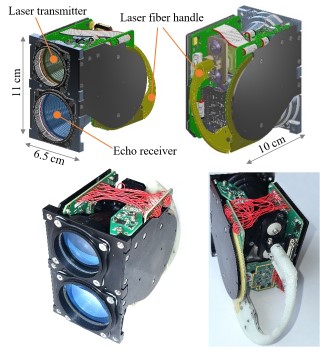
In this study, the authors focused on the quantitative evaluation of the expected performance of the developed compact LRF module (Fig. 1) in cooperation with a small (2-inch diameter) CCR located at a distance of 10–30 km. However, the proposed model and entire methodology are not limited to this case study and can be applied to any other case.
The LRF module developed for the PIAST is based on the dToF technique. It uses a semiconductor laser with a fibre output. Such a solution was selected to obtain a highly uniform far-field beam spatial irradiance distribution. Bare semiconductor high-power pulsed lasers produce multi-mode, highly nonuniform output beams. The fibre pigtail provided a mode-mixing effect, leading to significant improvements in beam uniformity and circularity. An avalanche photodiode (APD) was used as the photodetector. In addition to APD, the application of a single-photon avalanche diode (SPAD) was considered [21]. However, the authors found it to be less suitable for the discussed application for the following reasons: first, SPAD is extremely sensitive to background light; therefore, very narrow spectral filtering must be used. However, this is not possible because the semiconductor laser used does not have a narrow linewidth. Additionally, its wavelength changed slightly owing to thermal shifts. The second method of suppressing the background light falling onto the detector is to narrow the field of view. However, in this aspect, the authors were also limited by a laser beam divergence (if the detector field of view decreased below this level, the signal level would be lost). Secondly, SPADs are manufactured as very small detectors in terms of their sensitive-area size (levels not exceeding 100 μm). To maintain the required field of view of such a detector, very short focal-length collecting optics are required. Simultaneously, these optics, in the case of the PIAST mission must have a diameter of approximately two inches to guarantee a sufficient echo signal level. Both of these aspects lead to unrealistically low 𝑓/# optics require-ments. Finally, it was not possible to find commercially available SPADs with space qualification certificates. It should also be noted that the developed LRF module is resistant to all background radiation sources (such as the Sun, Moon, and Earth). For this purpose, several tests were performed using a Sun simulator, both in terms of the disruption and destruction of the module.
The developed methodology of the LRF analysis, which is the main subject of this study, allowed the authors during the design process to determine a balance between the LRF size/weight/power and its performance. The goal of the authors’ model was to predict how LRF would cooperate with the CCR and how far it would be possible to measure the distance. This model was based on both theoretical and experimental assumptions. The main challenge in this approach is to generalise the rangefinder formula for non-Lambertian targets (LTG) and obtain the absolute values of the CCR back-reflection efficiency. The latter was performed using experimental measurements in which the CCR FFDP were compared with the Airy Disc diffraction pattern. Range performance analysis deals with the expected signal-to-noise ratio (SNR) in the LRF detection circuit as a response to the lidar echo produced by laser back-reflection from the CCR. The main goal was to obtain the SNR range dependence, which allows to assess the maximum possible range of detection and how it depends on the CCR tilt.
Theoretical range performance analysis
Signal to noise ratio in a detector circuit
Most LRFs measure the distance to the so-called LTG, which show diffuse [15] back-reflection of the laser into the full hemisphere. In addition, the catalogue cards of typical LRFs, when providing the maximum range of measurement, correspond to LTG of known size and reflectance. For example, if military LRFs are considered, it is a 2.3 m × 2.3 m size and a 20% reflectance square plate (which corresponds to a tank size representation). This approach is reasonable because despite most natural terrain objects not being perfectly Lambertian, they reflect light in a very similar (diffuse) manner.
Considering the fundamental equation allowing the assessment of LRF performance, the SNR range-dependence can be defined as the ratio of the signal voltage (𝑉𝑠) to the noise voltage (𝑉𝑛):
\( \mathrm{SNR}=\frac{V_s}{V_n} \) (1)
Both voltages depend on the type of LRF hardware and the environmental conditions. An APD detector is used in the developed LRF. The output was amplified using a wideband transimpedance amplifier. In this case, the equivalent circuit shown in Fig. 2 can be considered.

The amplifier output voltage in the transimpedance configuration is simply the product 𝑉out= 𝐼PH𝑅F. Thus, the voltage corresponding to the optical echo signal (useful signal voltage) is given by
\( V_s=P_{\mathrm{S}} S M R_{\mathrm{F}} \) (2)
where 𝑃S is the optical power of the echo signal captured by the detector, 𝑆 is the detector sensitivity, and 𝑀 is the avalanche coefficient. The output noise is composed of four components:
thermal noise:
\( V n_{\text {thermal }}=\sqrt{4 k T R_F f_2 \frac{\pi}{2}} \) (3)
input voltage noise:
\( V n_{V \mathrm{BN}, \mathrm{Amp}}=V_{\mathrm{EN}} \frac{C_{\mathrm{S}}+C_{\mathrm{M}}+C_{\mathrm{D}}+C_{\mathrm{F}}}{C_{\mathrm{F}}} \sqrt{f_3 \frac{\pi}{2}} \) (4)
input current noise:
\( V n_{I_{\mathrm{EN}, \mathrm{Amp}}}=I_{\mathrm{EN}} R_{\mathrm{F}} \sqrt{f_2 \frac{\pi}{2}} \) (5)
APD shot noise:
\( V n_{\text {APDShot }}=R_{\mathrm{F}} \sqrt{2 q B \frac{\pi}{2}\left[\left(P_{\mathrm{B}}+P_{\mathrm{S}}(z)\right) S+I_d\right] M^{2+x}} \) (6)
where 𝑘 – Boltzmann constant, 𝑇 – absolute temperature, 𝑉EN – equivalent voltage noise, 𝐼EN – equivalent current noise, 𝑞 – electron charge, 𝐵 – signal bandwidth, 𝑃B – background optical power received by detector, 𝑃S – signal optical power received by detector (optical echo power), 𝑥 – excess noise factor. The cutoff frequencies appearing in the above formulae are as follows:
\( f_2=\frac{1}{2 \pi R_{\mathrm{F}} C_{\mathrm{F}}} \) (7)
\( f_3=\frac{f_{\mathrm{CR}}}{\left(C_{\mathrm{S}}+C_{\mathrm{M}}+C_{\mathrm{D}}+C_{\mathrm{F}}\right) / C_{\mathrm{F}}} \) (8)
where 𝑓CR is the amplifier crossover frequency.
The noise components add incoherently; therefore, the total resultant noise is given by the following formula:
\( V_n=\sqrt{V n_{\text {thermal }}{ }^2+V n_{V_{\text {EN,AMP }}}{ }^2+V n_{I_{\text {EN,AMp }}}{ }^2+V n_{\text {APDShot }}{ }^2} \) (9)
By applying (2) and (9) to (1), the SNR range-dependence can be obtained as follows:
\( \operatorname{SNR}(z)=\frac{P_{\mathrm{S}}(z) \mathrm{SMR}_{\mathrm{F}}}{\sqrt{V_n}} \) (10)
It should be noted that the only factor in the above formula that makes the SNR range-dependent is the echo signal optical power. Therefore, the crucial part of each LRF design deals with the optimisation of the optical echo power PS according to the required maximum range of operation. In the considered space application, the authors’ rangefinder faced very large measurement distances. In such cases, the laser beam footprint is always significantly larger than that of the measured object. For this reason, the conventional rangefinders equation had to be modified, including this ‘cutting’ effect. In addition, it is important to determine how the measured object surface reflects light; this will be different for scattering surfaces (such as Lambertian) when compared to reflecting surfaces.
To evaluate the predicted performance of an LRF, a specific form of PS must be implemented in (10), and the expected maximum range of detection 𝑧max can be obtained from the threshold condition:
\( z_{\max }: \operatorname{SNR}\left(z_{\max }\right)=\mathrm{SNR}_{\min } \) (11)
where SNRmin is the minimum acceptable SNR, which still guarantees the detection of optical echo pulses.
Lidar echo-dependence on type of reflecting surface
For ‘small’ LTG, neglecting the imperfection of the optics and geometrical form factor [22, 23], the following equation can be used to predict how optical echo power 𝑃SLTG received from this type of target will depend on the range 𝑧:
\( P_{\mathrm{S}}^{\mathrm{LTG}}(z)=P_{\mathrm{p}} \frac{D_0^2 D_{\mathrm{TGT}}^2}{4 \theta^2 z^4} \rho \) (12)
where 𝑃p – output peak power of LRF laser pulse, 𝐷0 – equivalent diameter of receiving optics, 𝐷TGT – equivalent diameter the target, 𝜌 – target surface reflectance coeffi-cient, 𝜃 – LRF laser beam divergence (even well collimated laser beam shows certain finite divergence angle). Atmospheric extinction was omitted because it did not appear in cosmic space. For the same reason, the devastating impact of atmospheric turbulence [24] was neglected. Now, if, instead of the LTG, a CCR is consid-ered, the signal echo power 𝑃SCCR will be substantially larger, and equation (12) can be rewritten to the following equivalent general form:
\( P_{\mathrm{S}}^{\mathrm{CCR}}(z)=P_{\mathrm{p}} \frac{D_0{ }^2 D_{\mathrm{TGT}}{ }^2}{4 \theta^2 z^4} \xi_{\mathrm{CCR}}(z) \) (13)
where standard reflectivity 𝜌 appearing in (12) was replaced by 𝜉CCR, which the authors will refer to as CCR efficiency of lidar echo generation. to The similarity between (13) and (12) has been kept intentionally in order to be able to directly compare 𝜉CCR and 𝜌.
The explicit mathematical form of 𝜉CCR depends on the method a CCR back-reflection is modelled. In the case of a purely geometrical approach (no diffraction), the back-reflected optical beam cross-section has the shape of a circle twice the diameter of the retroreflector. This corresponds to the following efficiency of the CCR back-reflection:
\( \xi_{\mathrm{CCR}}^{(\mathrm{GEO})}=\eta_{\mathrm{CCR}}\left(\frac{z}{D_{\mathrm{CCR}}}\right)^2 \) (14)
where 𝜂CCR – retroreflector efficiency (corresponding to reflection/transmission losses), DCCR – retroreflector diame-ter. It can be noticed how gigantic values the 𝜉CCR(GEO) can reach. For example, assuming a 2-inch diameter CCR, 1 km distance, and neglecting reflection/absorption losses within CCR (which is reasonable for AR coated TIR CCRs), one obtains 𝜉CCR(GEO)= 3.9 · 108. Thus, compared to the typical reflectance of standard Lambertian surfaces (𝜌= 0.1 − 0.7), in this case retroreflector provides ~ 9 orders of magnitude stronger optical echo power 𝑃SCCR≫𝑃SLTG.
Unfortunately, the geometrical approach is valid for relatively short detection ranges (𝑧≪𝑧short) where diffraction effects can be omitted [22]. For larger distances, owing to the wave-like nature of light, the geometrical model was overly optimistic. Assuming a simple limiting condition, the circular aperture diffraction effects double the diameter of the previously discussed geometric echo circular spatial footprint, and the following equation can be obtained:
\( z_{\text {short }}=\frac{D_{\mathrm{CCR}}^2}{\lambda} \) (15)
where 𝜆 is the wavelength of laser.
Assuming as an example a 2-inch diameter CCR and a 1 μm wavelength, one obtains 𝑧short= 2.8 km. Thus, for space applications where multi-km distances of detection are considered, it is necessary to consider diffraction effects. To include them in the LRF range performance modelling, it was necessary to find the appropriate formula for CCR 𝜉CCR(DIFFR) back-reflection efficiency which would cover the diffraction effects, and which could be implemented in (13). Formally, this efficiency is directly associated with a CCR FFDP, which can be factorized as follows:
\( I_{\mathrm{CCR}}{ }^{(\mathrm{FFDP})}(u, v)=I_{0, \mathrm{CCR}}^{(\mathrm{FFDP})} f(u, v) \) (16)
where 𝐼CCR(FFDP)(𝑢,𝑣) is the angular distribution of the CCR FFDP radiant intensity, 𝐼0,CCR(FFDP) is the on-axis CCR FFDP intensity, and 𝑓𝑓(𝑢𝑢,𝑣𝑣) is the dimensionless angular factor. From the viewpoint of the LRF analysis, only 𝐼0,CCR(FFDP) is important. In this case, the power received by the LRF detector is expressed as:
\( P_{\mathrm{S}}^{\mathrm{CCR}}(z)=I_{0, \mathrm{CCR}}{ }^{(\text {FFDP })} \cdot \frac{\pi D_0^2}{4 z^2} \) (17)
Regarding the unknown 𝐼0,CCR(FFDP), the following proportionality can be deduced:
\( I_{0, \mathrm{CCR}}{ }^{(\mathrm{FFDP})} \sim P_{\mathrm{p}} \frac{D_{\mathrm{CCR}}{ }^2}{\theta^2 z^4} \) (18)
Merging (17) with (18) and aiming to obtain a formula similar to (13), the following can be obtained:
\( P_{\mathrm{S}}^{\mathrm{CCR}}(z)=P_{\mathrm{p}} \frac{D_0{ }^2 D_{\mathrm{CCR}}{ }^2}{4 \theta^2 z^4} \xi_{\mathrm{CCR}}^{(\mathrm{DIFFR})}(z) \) (19)
The authors introduced here the factor 𝜉CCR(DIFFR) – CCR efficiency of lidar echo generation which includes the diffraction effects and can be expressed by the following formula:
\( \xi_{\mathrm{CCR}}{ }^{(\mathrm{DIFFR})}(z)=\left(\frac{\pi \theta^2}{P_{\mathrm{p}}}\right)\left(\frac{z}{D_{\mathrm{CCR}}}\right)^2 I_{0, \mathrm{CCR}}^{(\mathrm{FFDP})} \) (20)
Thus, to use this scheme in practice, the CCR FFDP absolute radiant intensity in its axial region 𝐼0,CCR(FFDP) must be determined, which is not straightforward. Experi-mental determination requires the calibration of both the sensor and the entire optical train. Alternatively, the pure experimental validation of CCR, directly in a long-range setup simulating real scenarios, is hardly feasible owing to the required a.m. multi-km range and atmospheric turbulence effects which distort the obtained results in the Earth’s environment (not needed to be considered in the space environment). 𝐼0,CCR(FFDP) can also be theoretically determined by simulating the CCR FFDPs [17, 20]. However, this remained a mathematical challenge. There are different studies dealing with this issue, providing different results. There are three main reasons for not limiting the authors’ modelling to available theoretical studies:
- The main drawback of the available theoretical models is the idealisation of CCR. It is difficult to simulate all the imperfections of real-life CCRs, especially because these imperfections are hardly measurable and are not provided by manufacturers. However, even the minor ones will have an impact on the CCR FFDP, resulting in a decreased SNR of the LRF.
- In their experiments, the authors observed significant discrepancies from theoretical distributions, especially for non-zero inclination angles.
- Theoretical models are based on idealised monochro-matic, coherent, polarised, flat or spherical wavefronts. In the authors’ LRF module, a fibre-coupled semicon-ductor high-power pulsed laser was used. It does not provide polarised and single-mode beams but rather corresponds to a partially coherent extended source of a quasi-monochromatic radiation.
Therefore, to obtain the results for real CCRs, the authors implemented a new hybrid experimental approach. This is based on a specific comparative calibration of the authors’ measurement setup, where the Airy diffraction pattern is used as a reference. Thus, without any knowledge of the total transmission of the optics and the sensitivity of the applied sensor, the authors first measured the FFDP of a circular flat mirror of the same size as the CCR. This FFDP corresponded to a well-described Airy pattern. Then, the FFDPs of the CCRs, which will be used in cooperation with the authors’ LRF in space missions, were measured in the same setup. To obtain the absolute values of 𝐼0,CCR(FFDP), the CCR FFDP obtained was referenced to the level of the previously measured Airy pattern. This approach is analytically specified as follows.
First, instead of dealing directly with the CCR, the authors considered an LRF cooperating with a flat circular mirror that is perfectly aligned (perpendicular to the LRF laser beam). The obtained back-reflected optical echo corresponded to a well-known and analytically described Airy pattern (AFFDP). From the perspective of a laser range finding technique, as mentioned previously, only the axial power distribution determines the performance. For AFFDP, the on-axis irradiance E0,AFFDP can be expressed by the following equation [25]:
\( E_{0, \mathrm{AFFDP}}(z)=\frac{P_r A_m}{\lambda^2 z^2} \) (21)
where 𝑃𝑟 – diffracted optical power, 𝐴𝑚 – surface area of diffracting circular aperture, 𝜆 – wavelength of light, 𝑧 – range. Assuming that the mirror has the same diameter as the CCR and adopting (21) into the LRF reality, after several mathematical operations, the following can be stated:
\( E_{0, \text { Mirror }}(z)=\frac{\pi P_{\mathrm{p}} \rho D_{\mathrm{CCR}}{ }^4}{4 \lambda^2 z^4 \theta^2} \) (22)
where 𝜌 – the mirror surface reflectance coefficient for the wavelength 𝜆.
Accordingly, the optical echo power received from this type of target can be obtained simply by multiplying 𝐸0,Mirror by the receiving aperture surface area. By writing the resultant equation in a form similar to (13), the following is obtained:
\( P_{\mathrm{S}}^{\text {Mirror }}(z)=P_{\mathrm{p}} \frac{D_0^2 D_{\mathrm{CCR}}{ }^2}{4 \theta^2 z^4} \cdot \frac{\pi^2 \varrho D_{\mathrm{CCR}}{ }^2}{4 \lambda^2} \) (23)
By comparing (13) and (23), the echo back-reflection efficiency can be introduced in the case of a circular mirror target (with the same diameter as the CCR):
\( \xi_{\text {Mirror }}=\frac{\pi^2 \varrho D_{\mathrm{CCR}}^2}{4 \lambda^2} \) (24)
It should be noted that the above formulas include diffraction effects; therefore, (23), when implemented in (10), allows the range performance analysis of the LRF to cooperate with a small mirror target, even for very long detection distances. However, flat mirrors are not used in space because the considered performance can be obtained only in the case of perfect alignment, which is not achiev-able in practical applications. This is the main reason why CCRs, which do not require alignment, are heavily used.
In the authors’ analysis, the LRF performance in the case of a small mirror target was fundamental for other reasons. In the far-field region, light reflected from a circular flat mirror shows the irradiance distribution defined by the Airy pattern, which is fully defined by analytical formulae. The measured Airy distribution intensities can be used as an absolute reference for similar measurements of FFDPs of other components in the same optical setup. In other words, with such a reference, one does not need to know the hardware parameters of this setup and can still obtain absolute measurements of the FFDPs of the CCRs. Thus, a so-called correction factor ζ is introduced. It is the ratio of the measured axial irradiance of CCR FFDP and FFDP of a flat circular mirror of the same diameter, additionally corrected by ρ to include the effect of a reflectance coefficient smaller than the unity of the reference mirror:
\( \zeta=\varrho \cdot\left[\frac{E_{0, \mathrm{CCR}}}{E_{0, \mathrm{AFFDP}}}\right]_{\text {(measured) }} \) (25)
By applying 𝜁𝜁, the equivalent of (19) can be established for CCR target as follows:
\( P_{\mathrm{s}}^{\mathrm{CCR}}(z)=P_{\mathrm{p}} \frac{D_0{ }^2 D_{\mathrm{cCR}}{ }^4 \pi^2 \eta_{\mathrm{CCR}}}{16 \lambda^2 \theta^2 z^4} \cdot \zeta \) (26)
It should be noted, that to use (26), one has to determine 𝜁. This is not problematic; however, because it does not require absolute measurements, it is based on a compara-tive approach.
Algorithm architecture and implementation
In the previous section, the range dependence (26) was obtained by modelling the expected optical echo power received by the LRF from the CCR, including the diffraction effects. This equation can be implemented in (10) for SNR(𝑧) evaluation and maximum theoretical range determination according to the condition in (11), as presented in Fig. 3.
To use this methodology, the correction factor had to be determined, which in our methodology was obtained experimentally. The FFP measurements were performed by applying the focal plane (Fourier plane) technique, which allowed the authors to obtain the far-field (Fraunhofer) diffraction pattern of light by measuring its distribution in the focal plane of the telescope [26]. This allows the avoidance of unrealistic multi-km-range measurements of FFDP, which in the conditions of the Earth’s atmosphere, would be pointless.

The experimental setup is shown in Fig. 4. The laser source was a fibre-coupled pulsed semiconductor laser operating at a wavelength of 905 nm. Its multi-mode beam is spatially filtered by a microscope objective (MO) cooperating with 10 μm pinhole (PH). A collimator is then used to create a flat wavefront, which then goes (through a transparent optical wedge) to the tested CCR or, alternatively, to reference round mirror (MF). The light reflected from the CCR or MF travels back, and part of it is reflected from the wedge faces. A telescope is then used to create an FFDP of the light field reflected from the CCR or MF. The FFDPs were captured using a CMOS camera whose FPA was positioned precisely in the focal plane of the telescope. The telescope was aligned in such a way that only the front face wedge reflection was recorded. The results were collected for a predefined set of inclination angles. In addition, the FFDP of the light reflected from a circular mirror (Airy diffraction pattern) positioned perpendicular to the telescope axis was captured.

As mentioned in the previously described methodology, the mirror had the same diameter as the CCR and was placed exactly at the same part of the laser beam as the CCR. Based on a comparison between the measured CCR FFDPs and the mirror, the FFDP correction factor was calculated. This allowed the authors to proceed through PS(z) and SNR(z) up to the zmax calculation. An example of the FFDPs recorded in the experimental setup is shown in Fig. 5.
\( \operatorname{SNR}(z)=\frac{P_{\mathrm{S}}(z) \mathrm{SMR}_{\mathrm{F}}}{\sqrt{V_n}} \) (27)

In addition, there was a significant dependence of the spatial distribution of the CCR FFDP irradiance on the angle at which the radiation fell on the retroreflector [the fell on the retroreflector [the angle of incidence (AOI)]. The greater the AOI, the greater the stretch of the FFDP and,thus, the resulting decrease in the irradiance. Measurements were performed for various AOIs and different integration times of the CMOS sensor. The quantitative evaluation of ζ required the recording of the unsaturated images both reference Airy Disc and the CCR FFDPs.
The selected results in terms of the calculated correction factors are listed in Table 1. According to the proposed methodology (Fig. 3), these results were applied in (26) for the echo signal optical power estimation, which was then used in (10) to obtain the SNR curves (Fig. 6).
Table 1.
Experimentally determined 𝜁𝜁 values for different CCR AOIs.
𝜷\𝜶 |
0° |
5° |
10° |
15° |
20° |
25° |
30° |
35° |
0° |
0.63 |
0.44 |
0.32 |
0.22 |
0.16 |
0.08 |
0.05 |
0.03 |
5° |
0.45 |
0.38 |
0.30 |
0.21 |
0.14 |
0.07 |
0.05 |
0.03 |
10° |
0.33 |
0.31 |
0.24 |
0.18 |
0.12 |
0.06 |
0.04 |
0.02 |
15° |
0.22 |
0.20 |
0.17 |
0.13 |
0.08 |
0.05 |
0.03 |
0.02 |
20° |
0.16 |
0.15 |
0.12 |
0.08 |
0.06 |
0.04 |
0.03 |
0.01 |
25° |
0.07 |
0.06 |
0.05 |
0.05 |
0.04 |
0.03 |
0.02 |
0 |
30° |
0.05 |
0.04 |
0.04 |
0.03 |
0.03 |
0.02 |
0.01 |
0 |
35° |
0.03 |
0.03 |
0.02 |
0.02 |
0.01 |
0 |
0 |
0 |

The key hardware parameters of the LRF setup are listed in Table 2. Assuming the minimum acceptable SNR at the level of SNRmin = 10, the expected maximum ranges of LRF operation were determined (such threshold is reasonable for direct or ‘single-shot’ detection method). This was performed for all the investigated angular orientations of the CCR. Table 3 presents the results of the study. It can be seen that the LRF maximum expected range of operation strongly depends on CCR angular orientation with respect to the incoming laser beam. It is also evident that for tilts that create total internal reflection, the CCR does not reflect light back, and its retroreflection effect does not exist. Nevertheless, within a cone of 30°, 15–40 km appears achievable for a single CCR. To extend the angular sector of the satellite possible orientations beyond the mentioned cone and maintain the distance measurements possible, several CCRs are deployed on each side of the satellite in such a way that sectors covered by individual CCRs mutually overlap.
Table 2.
Numerical parameters used for PIAST LRF performance simulation.
Parameter |
Symbol |
Value |
Maximum peak power of the laser pulse (can be tuned electronically on-orbit) |
𝑃p |
100 W |
Pulse width of the laser pulse |
𝜏p |
30 ns |
Wavelength of the laser |
𝜆 |
905 nm |
Laser pulse repetition frequency |
𝑓p |
2 kHz |
Diameter of LRF collecting optics |
𝐷𝐷0 |
50.8 mm |
Diameter of CCR |
𝐷CCR |
50.8 mm |
Laser beam divergence |
𝜃 |
5 mrad |
Optical efficiency of CCR |
𝜂CCR |
0.92 |
Feedback resistance |
𝑅F |
100 kΩ |
Electronic bandwidth |
𝑞 |
16.6 MHz |
Power of optical background received by the detector |
𝑃B |
10 nW |
Photodiode dark current |
𝐼d |
2 nA |
Multiplication factor |
𝑆 |
50 |
Excess noise factor |
𝑥 |
0.3 |
Sensitivity |
𝑆 |
0.45 AW−1 |
Temperature |
𝑘 |
300 K |
Photodiode capacitance |
𝐶S |
1 pF |
Amplifier common-mode capacitance |
𝐶M |
0.5 pF |
Amplifier differential-mode capacitance |
𝐶D |
0.3 pF |
Feedback capacitance |
𝐶F |
0.095 pF |
Equivalent current noise |
𝐼EN |
1 pA/Hz1/2 |
Equivalent voltage noise |
𝑉EN |
2.5 nV/Hz1/2 |
Amplifier crossover frequency |
𝑓CR |
5.5 GHz |
Table 3.
Calculated maximum ranges 𝑧max (km) of PIAST LRF for different CCR AOIs (𝛼𝛼, 𝛽𝛽).
𝜷\𝜶 |
0° |
5° |
10° |
15° |
20° |
25° |
30° |
35° |
0° |
41.3 |
37.8 |
35.0 |
31.9 |
29.4 |
24.8 |
22.0 |
19.4 |
5° |
38.0 |
36.5 |
34.4 |
31.5 |
28.5 |
24.0 |
22.0 |
19.4 |
10° |
35.2 |
34.7 |
32.6 |
30.3 |
27.4 |
23.1 |
20.8 |
17.5 |
15° |
31.9 |
31.1 |
29.9 |
28.0 |
24.8 |
22.0 |
19.4 |
17.5 |
20° |
29.5 |
29.0 |
27.4 |
24.8 |
23.1 |
20.8 |
19.4 |
14.7 |
25° |
24.0 |
23.1 |
22.0 |
22.0 |
20.8 |
19.4 |
17.5 |
- |
30° |
22.0 |
20.8 |
20.8 |
19.4 |
19.4 |
17.5 |
14.7 |
- |
35° |
19.4 |
19.4 |
17.5 |
17.5 |
14.7 |
- |
- |
- |
Apart from SNR(z) curves for CCR target, Fig. 6 contains the curves for the theoretical ‘non-diffracting’ CCR target and the LTG, for comparison. The former shows the strength of the diffraction effect with respect to the LRF performance during a long-range operation (at a distance of 30 km, diffraction is responsible for a reduction of one order of magnitude in the echo signal). Not surprisingly, because of the latter, it is evident that without CCR imple-mentation, the maximum LRF measurement range would be a few orders of magnitude smaller, thus not meeting the requirements of the PIAST mission. In such cases, the entire satellite body should be considered the measured target. Nevertheless, even for the highest reflectance coeffi-cients that can be hypothetically considered for satellite surfaces, considering the maximum acceptable parameters associated with the power and size of the LRF, the maximum range would be significantly lower than required (according to the authors’ calculations, it would not exceed 1 km).
Conclusions
In this study, a detailed treatment of the methodology was used to evaluate the expected range performance of the authors’ CCR-assisted space LRF. To the best of the authors’ knowledge, such an end-to-end scheme has not yet been reported. Typically, the performance is modelled for situations in which the LRF cooperates with the Lambertian surface. It leads to the standard ‘rangefinder equation’ or ‘radar equation’. Here, the authors extend this approach to a space scenario, in which the LRF measures the distance to the CCR located on a distant object (another satellite). Because of the long-range operation, it was necessary to consider the diffraction effects resulting from the CCR laser back-reflection, which manifested as a FFDP. CCR FFDPs theoretical models have been discussed in few papers; however, the results are either more qualitative than quantitative or do not precisely overlap. Therefore, the authors’ approach is based on a dedicated experimental procedure for quantitative CCR FFDP evaluation.
The proposed methodology is based on the fusion of experimentally validated factors and theoretical modelling. The experimental part of this work deals with the determination of the lidar back-reflection cross-section of the CCR, including the diffraction effects. This was accomplished by implementing the focal plane technique, which allows observation of the FFDP in the focal plane of a telescope. The CCR FFDPs were compared with the FFDP of a circular flat mirror with known parameters (FFDP corresponding to the Airy Disc pattern). This allowed the authors to verify how a large correction factor should be considered in the equations governing the LRF SNR for CCR-assisted target measurement. This correction factor was determined for several angular tilts of the CCR, which allowed a quantitative analysis of the range loss that can be expected in the case of larger deviations from the perpendicular incidence of the laser on the CCR. The proposed approach also deals in detail with the noise factors resulting from both the detection process and the trans-impedance amplifier used. The described method was used to verify the expected performance of the LRF module developed for the PIAST program. In this mission, the LRF is planned to cooperate with 2-inch diameter CCRs. The obtained results are summarised in Table 3, where the maximum expected range of the measurement values is obtained for various angular tilts of the CCR for the incoming laser beam. It can be seen that for the most favourable situations (CCR oriented nearly orthogonal to the LRF laser beam), ranges of about 40 km can be expected. Obviously, the more the CCR is tilted, the smaller the maximum achievable range. Considering the largest acceptable tilts, that is, those about 30° off axis, the LRF range will drop to approximately 15 km. If CCR tilt exceeds this threshold, there would be a sudden loss of range measurement capability due to the loss of retro reflex effect (caused by total internal reflection inside CCR). To avoid such ‘dead zones’ situations, the satellites will be equipped with several CCRs spaced at certain angular distances from each other in such a way that their corresponding cones of acceptance will partially overlap.
Acknowledgements
This work was supported by Polish Centre for Research and Development (NCBiR) under PIAST (Polish ImAging SaTellites) project. Grant no. DOB SZAFIR/10/A/022/01/2021.
References
-
Laser Ranging Interferometer. GRACE-FOhttps://gracefo.jpl.nasa.gov/laser-ranging-interferometer/
-
Jang, Y. S. & Kim, S. W. Distance measurements using mode- locked lasers: A review. Nanomanufacturing Metrol. 1, 131–147 (2018). https://doi.org/10.1007/s41871-018-0017-8
-
Ke, J.-Y. et al. Long distance high resolution FMCW laser ranging with phase noise compensation and 2D signal processing. Appl. Opt. 61, 3443–3454 (2022). https://doi.org/10.1364/AO.454001
-
Bender, P. L. Laser measurements of the lunar distance. Rev. Geophys. 13, 271–272 (1975).https://doi.org/10.1029/RG013I003P00271
-
Bender, P. L. et al. The lunar laser ranging experiment. Science 182, 229–238 (1973). https://doi.org/10.1126/science.182.4109.229
-
Dickey, J. O. et al. Lunar laser ranging: A continuing legacy of the Apollo program. Science 265, 482–490 (1994). https://doi.org/10.1126/SCIENCE.265.5171.482
-
Schillak, S. et al. Analysis of the results of the Borowiec SLR station (7811) for the period 1993–2019 as an example of the quality assessment of satellite laser ranging stations. Sensors 22, 616 (2022). https://doi.org/10.3390/S22020616
-
Plotkin, H. H., Johnson, T. S., Spadin, P. & Move, J. Reflection of ruby laser radiation from explorer XXII. Proc. IEEE 53, 301–302 (1965). https://doi.org/10.1109/PROC.1965.3694
-
Degnan, J. J. A tutorial on retroreflectors and arrays used in satellite and lunar laser ranging. Photonics 10, 1215 (2023). https://doi.org/10.3390/photonics10111215
-
McGarry, J. F. et al. NASA’s satellite laser ranging systems for the twenty-first century. J. Geod. 93, 2249–2262 (2019). https://doi.org/10.1007/s00190-018-1191-6
-
Dell’Agnello, S. et al. Creation of the new industry-standard space test of laser retroreflectors for the GNSS and LAGEOS. Adv. Space Res. 47, 822–842 (2011). https://doi.org/10.1016/j.asr.2010.10.022https://doi.org/10.1016/j.asr.2010.10.022
-
Liu, X. et al. Photon-limited single-pixel imaging. Opt. Express 28, 8132–8144 (2020). https://doi.org/10.1364/OE.381785
-
Williams, J. G., Turyshev, S. G., Boggs, D. H. & Ratcliff, J. T. Lunar laser ranging science: Gravitational physics and lunar interior and geodesy. Adv. Space Res. 37, 67–71 (2006). https://doi.org/10.1016/J.ASR.2005.05.013
-
Amann, M.-C., Bosch, T. M., Lescure, M., Myllylae, R. A. & Rioux, M. Laser ranging: a critical review of unusual techniques for distance measurement. Opt. Eng. 40, 10–19 (2001). https://doi.org/10.1117/1.1330700
-
Koenderink, J. J., van Ginneken, B. & Stavridi, M. Diffuse and specular reflectance from rough surfaces. Appl. Opt. 37, 130–139 (1998). https://doi.org/10.1364/AO.37.000130
-
Kruapech, S. & Widjaja, J. Laser range finder using Gaussian beam range equation. Opt. Laser Technol. 42, 749–754 (2010). https://doi.org/10.1016/J.OPTLASTEC.2009.11.020
-
Murphy, T. W. & Goodrow, S. D. Polarization and far-field diffraction patterns of total internal reflection corner cubes. Appl.>Opt. 52, 117–126 (2013). https://doi.org/10.1364/AO.52.000117
-
Goodrow, S. D. & Murphy, T. W. Effects of thermal gradients on total internal reflection corner cubes. Appl. Opt. 51, 8793–8799 (2012). https://doi.org/10.1364/AO.51.008793
-
Azzam, R. M. A. & Liu, J. Polarization properties of corner-cube retroreflectors: theory and experiment. Appl. Opt. 36, 1553–1559 (1997). https://doi.org/10.1364/AO.36.001553
-
Kalibjian, R. Output polarization states of a corner cube reflector irradiated at non-normal incidence. Opt. Laser Technol. 39, 1485– 1495 (2007). https://doi.org/10.1016/J.OPTLASTEC.2007.01.006
-
Villa, F., Severini, F., Madonini, F. & Zappa, F. SPADs and SiPMs arrays for long-range high-speed light detection and ranging (LiDAR). Sensors 21, 3839 (2021).https://doi.org/10.3390/s21113839
-
Wojtanowski, J. Cancelling lidar echo signal 1/range2 dependence and geometrical form factor shaping by the application of freeform optics. Opt. Laser Technol. 125, 106011 (2020). https://doi.org/10.1016/J.OPTLASTEC.2019.106011
-
Wojtanowski, J., Zygmunt, M., Traczyk, M., Mierczyk, Z. & Jakubaszek, M. Beam forming optic aberrations’ impact on maximum range of semiconductor laser based rangefinders. Opto- Electron. Rev. 22, 152–161 (2014). https://doi.org/10.2478/s11772-014-0191-1
-
Mahmood, A. S. An approach to investigating the feasibility of free- space optical communication technology deployment under scintillation effects. Opto-Electron. Rev. 31, e147037 (2023). https://doi.org/10.24425/OPELRE.2023.147037
-
Hecht, E. Diffraction. in Optics 467–471 (Addison Wesley, San Francisco, 2002).
-
Goodman, J. W. Wave-Optics Analysis of Coherent Optical Systems. in Introduction to Fourier Optics 96–108 (McGraw-Hill, Boston, 1996).